Two-Phase BLDC Motors
Motivation
For sensorless operation of BLDC motors, the six-step commutation based on back EMF zero crossing is simple and effective. This method has been intensively studied and widely applied. But detection of the zero crossing becomes difficult when both the rotational speed and PWM frequency are high (say, 180 krpm and 100 kHz). One solution is to make the bus voltage variable so that the three-phase full bridge does not need to perform PWM. Another is to use two-phase motors.
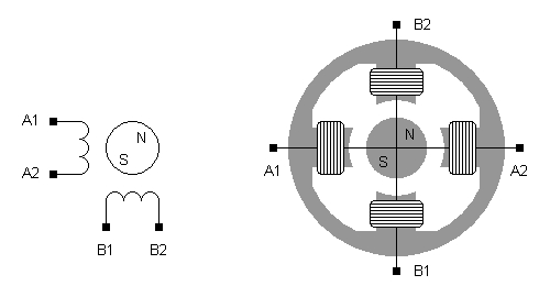
Shown below is the symbol of two-phase BLDC motors and a motor configuration. There are two phase-windings and four wire-terminals. The two phases are orthogonal in space, magnetically independent, and electrically insulated. Because of the insulation, while one phase is being driven in PWM, back EMF zero crossing of the other can be precisely detected.
Commutation sequence
With a trapezoidal phase current two-phase motors generally exhibit higher torque ripples than three-phase motors. But this is not a problem in low-power high-speed applications, and it is just for such applications that we have turned to two-phase motors. Our concern is that the phase current should have acceptable wave forms.
For two-phase motors each phase is driven by an H-bridge. We only need to consider one of the two phases, the other is the same except a 90° phase shift. According to the back EMF, the H-bridge operates either in PWM drive or let the phase float. The commutation sequence is shown below. A lead angle θ is introduced to let the phase current align with the back EMF.

Using the commutation sequence we have tested a number of different two-phase motors. The phase current wave forms turn out to be well acceptable. Only at low speed and very low motor load do the wave forms become unpleasant.
Remarks
For two-phase motors we have to use two H-bridges or eight transistors, while for three-phase motors six transistors are enough. But two-phase motors ease the detection of back EMF zero crossing. If we make the bus voltage variable we also need additional transistors as well as a power inductor.
Two-phase motors are simple. In concentrated winding configuration, the minimum number of coils is four for two-phase motors, and six for three-phase motors. Modeling and control of two-phase motors are especially simple since the two phases are independent.