Sensing by Switching Drive
Using switching drive
Most displacement sensors involve a sine-wave carrier signal and some kind
of demodulation. In our sensors we use switching drive: the sensing probe is driven by a square-wave voltage, and a baseband displacement signal is readily available somewhere in the driving circuit. This largely simplifies the sensor electronics.
Switching drive also permits satisfactory sensor performances. This may not be the case in the past. It is the advent of better and better semiconductor components that enables switching circuits to behave almost ideally, and gives switching drive an opportunity.
The rest of this page briefly explains how switching drive is used for eddy-current, capacitive, and inductive displacement sensing. Detailed descriptions can be found from the references listed at the bottom of this page.
Eddy-current displacement sensing
The principle is explained using the electronic circuit shown below, where the sensing coil is similar to that of most eddy-current displacement sensors, the oscillator is an IC that gives a square-wave voltage, U is a dc power supply, C1 reduces the ripple in the load current, and C2 prevents dc current from flowing through the coil.
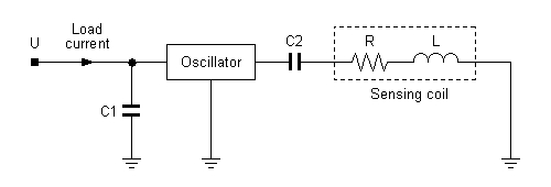
When a conductive target is placed near the coil, eddy current is induced in the target, and the eddy-current power loss is reflected at the load current. What is more, the power loss is dependent on the coil-target gap: smaller gaps give rise to higher power losses. In fact, the power loss or the load current is a continuous function of the gap. Thus the load current serves as a displacement signal.
Capacitive displacement sensing
Switching drive is also applicable to capacitive displacement sensing. In the circuit shown below, C represents the capacitance between a sensing probe and sensor target, R1 prevents the oscillator from having large transient current, and the others are the same as in the previous circuit. It is seen that C is cyclically charged and discharged, which gives rise to a power loss that is proportional to C. Thus the load current is a function of C or a function of the probe-target gap.
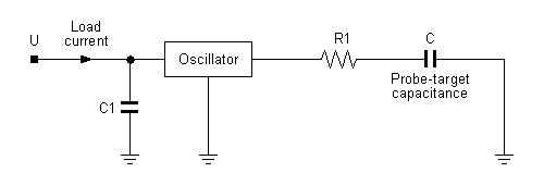
Note that the circuit only shows the principle. It is not practically useful. The operating current of the oscillator itself is usually much higher than that associated with the cyclic charge and discharge, resulting in very poor sensing performance.
Inductive displacement sensing
The principle is shown below. The oscillator and C1 are as described earlier. The inductors L1 and L2 represent a pair of inductances formed by an inductive displacement sensor (for a single motion axis). The sensor has such a configuration that L1 and L2 changes differentially as displacement takes place. Thus the amplitude of the output voltage is dependent on the displacement.
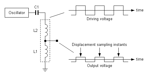
Suppose the sensor is used along with a controller. Let the oscillator have its frequency equal to the sampling frequency of the controller. Then the discrete-time signal obtained by sampling at the instants (see figure) is exactly what is needed by the controller.
Note that the sampling instants are at the mid-points between adjacent rising and falling edges, at which moments the inductors have zero magnetic flux. A non-zero flux will cause a certain amount of velocity (derivative of displacement with respect to time) to be superposed on the displacement. The sampling instants may be intentionally tuned to have a linear combination of displacement and velocity.
References
Lichuan Li, New displacement-sensing techniques for magnetic bearings, Proc 12th Int Symp Magnetic Bearings, Wuhan, China, Aug 2010.
Lichuan Li, Eddy-current displacement sensing using switching drive where baseband sensor output is readily available, IEEE Trans Instrumentation and Measurement, v57, n11, Nov 2008.