Magnetic Bearing Controller
Overview
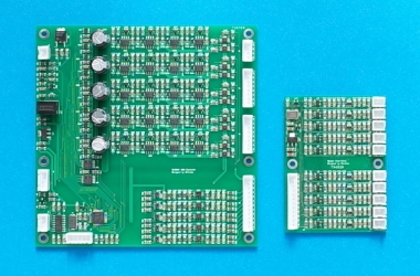
The controller (see figure below) is composed of two PCBs: a controller board (the bigger) and a sensor board (the smaller). It is for magnetic bearings that have five actively controlled axes. It has been applied to a few types of turbomolecular pumps with rotor masses (shaft + impeller) from 7 to 11 kg.
Features
• Simple, it is designed with simplicity in mind.
• Compact, controller board 130×130 mm2, sensor board 60×80 mm2.
• Low cost, a result of simplicity and compactness.
Controller board
The controller board includes ten channels of PWM power amplifiers, five channels of simultaneous sampling ADCs, an MCU, a digital I/O port, and a serial port. The controller board operates on a single dc power supply.
Each power amplifier is an H-bridge and gives a three-level PWM voltage output with bidirectional current. Thus the controller is applicable to both electrically biased and permanent magnet biased magnetic bearings. Of the PWM, the pulse widths are synchronously updated (no bad pulse).
The digital I/O port receives rotor speed pulses from a motor driver, and signals fault events of the magnetic bearing being controlled. The serial port exchanges data with a host device for tuning or normal operation.
Sensor board
The sensor board contains all the electronics for ten channels of eddy-current displacement sensors. The sensor board is connected to the controller board, while ten sensing coils are connected to the sensor board.
The ten sensing coils are grouped into five pairs, with each pair measuring a single displacement in differential mode (see figure below). In the axial direction, one coil may facing a non-movable dummy target.
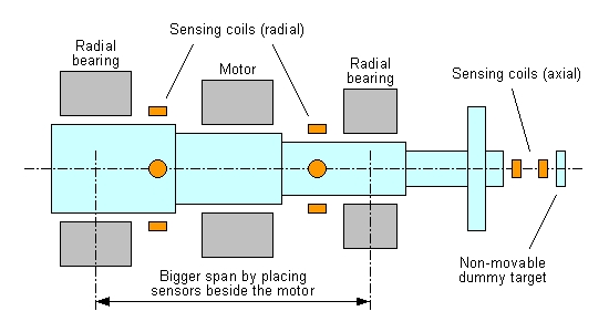
Many displacement sensors, especially the inductive type, should be placed far apart from the motor to avoid EMI. Our sensors are highly EMI-resistant and can be placed beside the motor to let the radial bearings have a bigger span.
Firmware
Presently the following modules have been implemented and tested.
1. Stabilization control, to suspend the rotor.
2. Clean-voltage control, to remove the rotor-imbalance-induced vibration.
3. Cross-feedback control, to cancel the gyroscopic effect.
4. Notch filters, to avoid self-excited structural vibrations.
5. Frequency response, to generate data for identification and sensitivity test.
6. Sensor calibration, to find sensor gains and offsets.
7. Parameter modification, to modify parameters on the fly.
8. Parameter download, to save parameters to controller flash memory.