AMB Motor, 150 krpm, 100 W
Background
The AMB motor is designed for rotor spinning machines (textile machinery). In such a machine there are many identical spinning heads working in parallel, and rotating at speeds up to 150 krpm. Presently most machines use friction drive, with a single friction belt driving all the heads. This is cost-effective but not energy-effective. Using individual AMB motors for each head can save energy significantly. But the cost is a concern. Our design has achieved a cost that is well acceptable.
The AMB motor
Shown below is the AMB motor and the associated electronics. The rotor is actively suspended by a pair of radial magnetic bearings biased using permanent magnets. The biasing flux passively stabilizes the axial direction. Radial displacements of the rotor are detected using inductive displacement sensors.
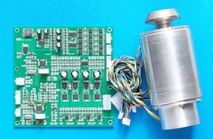
A two-phase BLDC motor is arranged at the back end (not between the two radial bearings). This reduces the motor-bearing EMI, and allows for using a single cylinder permanent magnet for the motor, both being highly preferred. The rotor can be accelerated from standstill to 150 krpm in about 10 sec, in which the peak power is about 300 W.
The PCB has a size of 130×130 mm2 and hosts both a magnetic bearing controller and a motor driver. The controller and driver have their own MCUs, and share a single dc power supply connected to the board. Operation is by sending commands to the motor MCU via a serial link. The two MCUs communicate via an on-board serial link.